

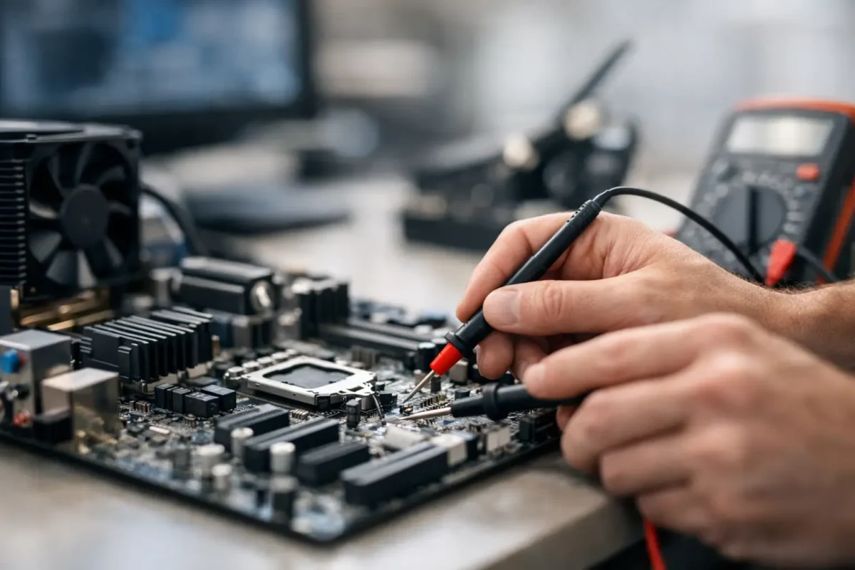
A computer can look completely dead while the real failure is one shorted component smaller than a grain of rice. That is why a proper guide to motherboard diagnostics starts with evidence, not guesswork. Replacing a power supply, RAM kit, or motherboard without isolating the fault can waste money and, in some cases, make data recovery or repair harder.
At Amazing Technology Group, we approach failed desktops and laptops the same way we approach difficult console and professional electronics repairs: establish the symptom, verify the basics, follow the power path, and test the board at the level where the failure actually lives. The process changes depending on the device, but the discipline does not.
Start With the Exact Symptom
“Won’t turn on” is not a diagnosis. A system that has no lights, no fan movement, and no response to the power button has a very different fault path than a PC that powers on, cycles repeatedly, or runs normally with no image on the monitor.
Before opening anything, document what happens when power is applied. Does the charging light come on? Do fans spin for a second? Is there a beep code, debug LED, or motherboard Q-Code? Did the failure happen after a liquid spill, power outage, BIOS update, overheating event, or hardware upgrade? These details narrow the field fast.
For desktop systems, confirm the outlet, power cable, power supply switch, and monitor input first. For laptops, test with a known-good charger of the correct voltage and wattage. A weak adapter can imitate a board failure, especially when a laptop powers on briefly but shuts down as soon as it tries to charge the battery or initialize the processor.
Make the System Safe Before Testing
Motherboard work is not the place for random probing or repeated power cycles. Disconnect AC power, remove the battery when practical, and discharge residual power before removing components. Use ESD protection when handling boards, memory, graphics cards, and storage devices.
Never bypass a blown fuse with wire or foil. Never keep trying to start a board that has visible liquid contamination, burn marks, or a component that is heating abnormally. Those shortcuts can turn a repairable failure into damaged CPU, GPU, memory, or storage hardware.
If the system contains critical business files, customer records, project work, or irreplaceable photos, protect the drive before aggressive troubleshooting. A motherboard failure does not automatically mean data is lost, but repeated unstable boot attempts can complicate recovery.
Inspect the Board Before Replacing Parts
A careful visual inspection catches more than many people expect. Look for corrosion around USB ports, charging circuits, keyboard connectors, RAM slots, and fan headers. On desktops, check for damaged CPU socket pins, loose standoffs, cracked solder joints around heavy graphics cards, and bulging or leaking capacitors.
Smell can be useful too. Burned power circuitry often leaves a sharp electrical odor near the voltage regulation area, DC jack, or graphics power section. That does not identify the failed part by itself, but it tells a technician where to concentrate inspection and measurements.
Remove obvious variables. Disconnect external devices, extra drives, RGB hubs, add-in cards, and nonessential USB accessories. A shorted front-panel USB port, failed PCIe device, or damaged peripheral can hold down a power rail and make a healthy motherboard appear dead.
Follow the Power Path
Power diagnosis is the foundation of a serious motherboard diagnostic process. The question is not simply whether power enters the board. The question is where it stops.
On a desktop board, technicians first verify the power supply outputs and standby voltage. The 5V standby rail is especially important because it supports functions that remain active while the PC is shut down, including the power-button control circuit. If standby power is missing, the issue may be the power supply, cable, connector, or an input-stage problem on the motherboard.
If standby voltage is present but pressing the power button does nothing, testing moves to the front-panel switch circuit, power-management controller, and power-on signal. If the board starts and immediately shuts down, the next suspects include a shorted rail, failed MOSFET, damaged VRM component, CPU power issue, or a protection response from the power supply.
Laptop boards require a more detailed sequence. A healthy charger voltage must reach the DC-in circuit, pass the input protection stage, and reach the charging and power-management ICs. From there, always-on rails must be created before the system can respond to the power button. A failed input fuse, reverse-protection MOSFET, charging IC, or shorted capacitor can stop that chain at different points.
A multimeter is the basic tool here. Board-level work may also require a bench power supply, thermal camera, current meter, oscilloscope, and low-voltage injection equipment. These tools let a technician find abnormal resistance, voltage drop, or a component that turns into a heat source under controlled power.
Diagnose No-POST and No-Display Failures
A board that turns on is not necessarily booting. POST, or Power-On Self-Test, is the stage where the system initializes the CPU, memory, graphics, firmware, and connected hardware. Failure at this stage can look like a black screen, boot loop, frozen logo, or no keyboard response.
Start with a minimum configuration: motherboard, CPU and cooler, one known-good RAM module in the recommended slot, and integrated graphics if the processor supports it. Use a known-good display cable and monitor. If a dedicated graphics card is required, verify its PCIe power connectors and test it in another compatible system when possible.
Motherboard debug LEDs and speaker beep codes are valuable, but they are clues rather than final answers. A DRAM light may point to bad memory, yet the real cause could be a damaged CPU socket pin, failed memory power rail, corrupted BIOS, or a CPU with a bad memory controller. The same applies to VGA and CPU indicators.
Clear CMOS only after recording the original symptom and configuration. Resetting settings can solve a bad memory profile or unstable overclock, but it can also erase useful information about what changed. If a system was stable until a firmware update, a BIOS corruption or failed update process deserves serious attention.
Check Rails, Shorts, and Heat Patterns
This is where the work separates part swapping from actual electronics diagnosis. A technician checks for shorts to ground on key rails before applying full power. Extremely low resistance can indicate a failed capacitor, MOSFET, integrated circuit, or damaged power stage, although resistance values must be interpreted in context. Some processor and graphics rails naturally measure very low.
When a short is suspected, controlled voltage injection can help locate it. The failed part may warm faster than surrounding components and become visible through thermal imaging or freeze-spray testing. This method must be done with the correct voltage and current limit. Feeding the wrong voltage into a rail can destroy components that survived the original failure.
Voltage regulation modules deserve close attention in gaming PCs and workstations. These circuits convert incoming power into the precise low voltages required by the CPU, RAM, and GPU. Overheating, liquid exposure, failed fans, poor airflow, and unstable overclocking can stress VRM components over time. A dead MOSFET or controller IC may be repairable at the board level, but only after confirming it is the cause and not the victim of another fault.
Firmware, Charging, and Embedded Controllers Matter
Modern motherboards depend on more than visible power components. BIOS or UEFI firmware, embedded controllers, charging controllers, and security chips all participate in startup behavior. A laptop may show a charging light but ignore the power button because the embedded controller is not receiving a required signal. A desktop may power on with fans at full speed because firmware initialization is failing.
Firmware problems can sometimes be resolved through proper recovery or reprogramming. Other cases require reading and verifying the firmware chip directly, checking for corrupted data, or addressing the underlying hardware condition that caused the corruption. Reflashing blindly is not a cure-all. Wrong firmware, incorrect board revision data, or an unaddressed power fault can leave the system worse off.
Know When the Fault Is Beyond Home Testing
Basic isolation is useful: test known-good RAM, charger, power supply, monitor, cable, and storage device. Stop when testing requires soldering, voltage injection, component removal, or live measurements around dense power circuitry. That is the point where the right equipment and experience protect the board and your investment.
A good diagnostic report should explain the confirmed fault, the parts or board-level work required, the repair risk, and whether the repair makes financial sense. Sometimes a replacement board is the practical answer. Sometimes component-level repair costs less, preserves an expensive machine, and avoids the delays of sourcing an obsolete or proprietary board.
The best next move is simple: preserve the symptom, avoid unnecessary power cycles, and get the board tested before buying parts. A clear diagnosis turns a frustrating dead system into a repair decision based on facts.