

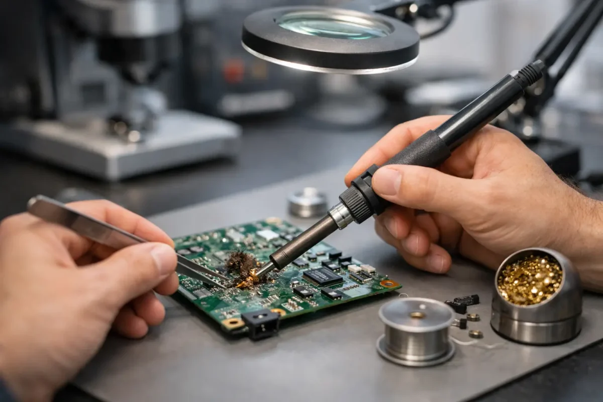
A failed device does not always need a new motherboard, control board, or main logic board. A lifted pad, corroded connector, cracked trace, or damaged charging circuit can stop an otherwise valuable PC, game console, DJ controller, or laptop in its tracks. Knowing how to repair damaged PCB problems starts with one rule: identify the actual failure before touching the soldering iron.
Board-level repair can save hardware that a parts-swapping shop may write off. It can also make a board worse when the wrong repair method is used. The difference is careful diagnosis, proper equipment, and knowing where a simple repair ends and advanced micro-soldering begins.
Start by Identifying the Type of PCB Damage
A printed circuit board, or PCB, is more than a surface holding components in place. Its copper traces carry power and data, pads create solder connections, vias move signals between layers, and internal layers may contain circuits you cannot see. Damage on the surface can be the visible symptom of a deeper fault.
Physical damage is usually the easiest place to begin. Look for broken connectors, missing components, cracked board edges, lifted pads, torn traces, bent USB or HDMI ports, and loose power jacks. A drop, impact, aggressive cable removal, or repeated flexing can cause these failures.
Liquid damage requires more caution. Even when a device starts after getting wet, moisture and residue can corrode copper, short fine-pitch components, and create failures weeks later. Green or white buildup around connectors, chips, and power circuitry is a warning sign. Battery leaks can cause similar damage and should be handled promptly.
Heat damage often appears as discolored board material, darkened solder joints, warped connectors, or burnt components. Do not assume the burnt part is the root cause. A capacitor, MOSFET, fuse, or power-management circuit may have failed because another part downstream shorted first.
Safety Comes Before Any PCB Repair
Disconnect all power before inspecting or testing a board. Remove the battery where possible, unplug chargers and external power supplies, and allow capacitors time to discharge. High-voltage power supplies, CRT equipment, industrial hardware, and some audio gear can retain dangerous voltage even after unplugging. Those repairs are not suitable for trial-and-error work.
Use ESD protection when working on sensitive electronics. A grounded mat and wrist strap reduce the risk of damaging components with static electricity. Work under good lighting and magnification. On modern consoles, laptops, and professional DJ equipment, many faults are too small to diagnose accurately with the naked eye.
Avoid powering a liquid-damaged board before it has been properly cleaned and inspected. Applying power to corrosion can turn a repairable problem into a burnt trace or failed integrated circuit.
How to Repair Damaged PCB Traces and Pads
Trace and pad repair is common after corrosion, impact damage, failed connector removal, or an attempted repair that used too much heat. The goal is not just to make electrical contact. The repair must be mechanically secure, correctly routed, and insulated from nearby circuits.
First, document the area with clear photos. This is especially useful if a wire, component, or connector has already come loose. Then clean the damaged section with high-percentage isopropyl alcohol and a soft brush. Cleaning removes flux residue, corrosion, and debris that can hide cracks or create leakage paths.
For a damaged trace, carefully expose a small section of clean copper on each side of the break. A fiberglass pen, precision scraper, or fine abrasive tool can remove the protective solder mask, but use a light touch. Digging too deeply can cut an adjacent trace or weaken the board further.
Tin the exposed copper with flux and a small amount of solder. For short, accessible breaks, soldering a thin insulated jumper wire from one healthy point to another is often stronger and more reliable than trying to rebuild the original trace. Route the wire cleanly, keep it away from moving parts and heat sources, and secure it with suitable board-safe adhesive when needed.
A lifted pad is more complicated because the pad may connect to a nearby trace, via, or internal layer. If the circuit has another accessible point on the same net, a jumper can restore the connection. If the pad is part of a connector, fine-pitch chip, or high-current circuit, the repair needs to withstand repeated stress. Simply attaching a wire to a loose pad rarely lasts.
After the repair, check continuity with a multimeter and verify that the repaired point is not shorted to adjacent pads or ground. Continuity alone does not prove the circuit is healthy, but it confirms whether the physical connection has been restored.
Replace Damaged Components Only After Testing
Burnt or visibly damaged parts should be replaced, but appearance is not enough to select a replacement. Component markings, board reference labels, schematics, boardview files, and measurements all help identify the correct value and function.
Start with basic checks. Measure fuses for continuity, check power rails for shorts to ground, inspect diodes for abnormal readings, and compare suspicious areas with a known-good section of the board when possible. A shorted ceramic capacitor can cause a console or laptop to show no power. Replacing only the blown fuse without finding that short will usually result in another blown fuse.
For connectors, confirm that the problem is actually the connector. A USB-C port may look damaged, but the fault could be in the charging controller, ESD protection circuit, or nearby power path. The same applies to HDMI ports on PS5 and Xbox consoles. A damaged port can be obvious, yet a missing signal may come from a torn trace or failed filter array behind it.
Use temperature-controlled soldering equipment, quality flux, and the correct tip size. Excessive heat can delaminate the board, damage plastic connectors, or pull pads from multilayer boards. Too little heat creates cold joints that may work briefly and fail under normal use.
Know When the Board Needs Advanced Repair
Some PCB damage is reasonable for an experienced hobbyist. A broken wire, a through-hole connector, or a simple trace break on a low-voltage board may be straightforward. Fine-pitch, multilayer, and high-density boards are a different category.
Professional help is usually the right call when the damage involves BGA chips, torn pads under a chip, internal-layer faults, water damage around dense power circuits, missing tiny components, or repeated no-power conditions after a basic repair. These jobs may require a microscope, hot-air rework station, preheater, thermal imaging, bench power supply, ultrasonic cleaning, and detailed circuit-level diagnostics.
Be cautious with common shortcuts. Reflowing a board with uncontrolled heat, baking it, flooding it with solder, or installing random jumper wires can permanently damage it. Heat may temporarily change a cracked solder joint, but it does not diagnose why the joint failed or whether the chip and board are still sound.
Test the Repair in Stages
Do not reassemble a device immediately after soldering. Inspect the work under magnification for bridges, loose solder balls, damaged neighboring parts, and uncleaned flux. Test continuity and resistance values again before applying power.
If a bench power supply is available, current-limited power-up testing can help catch a short before the device receives full power. Watch for abnormal current draw and localized heating. For liquid-damaged boards, this step can prevent additional damage while narrowing down the failed circuit.
Once the board powers normally, test every function affected by the repair. A laptop charging-port repair should be checked for charging, data, power delivery behavior, and physical cable fit. A repaired DJ controller should be tested for inputs, outputs, buttons, faders, and audio operation. A console HDMI repair needs video testing at stable resolution, not just a brief boot screen.
Repairing the Board Is Often the Best Value
Replacing an entire board may be fast, but it can be expensive, unavailable, or impractical when data, configuration, or device-specific programming is involved. Component-level repair can preserve the original hardware and correct the actual fault instead of replacing good parts along with bad ones.
That said, repairability depends on the board’s condition. Severe battery corrosion, extensive internal-layer damage, destroyed chip pads, or fire damage may make replacement the more dependable option. A real diagnosis should explain that trade-off clearly before money is spent.
When a valuable device has a damaged board, patience beats guesswork. Stop applying power, avoid improvised heat fixes, document what happened, and get the board evaluated by technicians who perform true in-house diagnostics. At Amazing Technology Group, difficult board failures are treated as engineering problems to solve, not automatic reasons to replace the device.